DEAD SMARTPHONE CHECKING PROCEDURE (INTRODUCTION)
Diagnosing a “dead” mobile phone requires a systematic approach, starting from external physical inspections and moving toward internal board-level measurements. This guide outlines the essential steps to identify the root cause of a non-responsive handset.
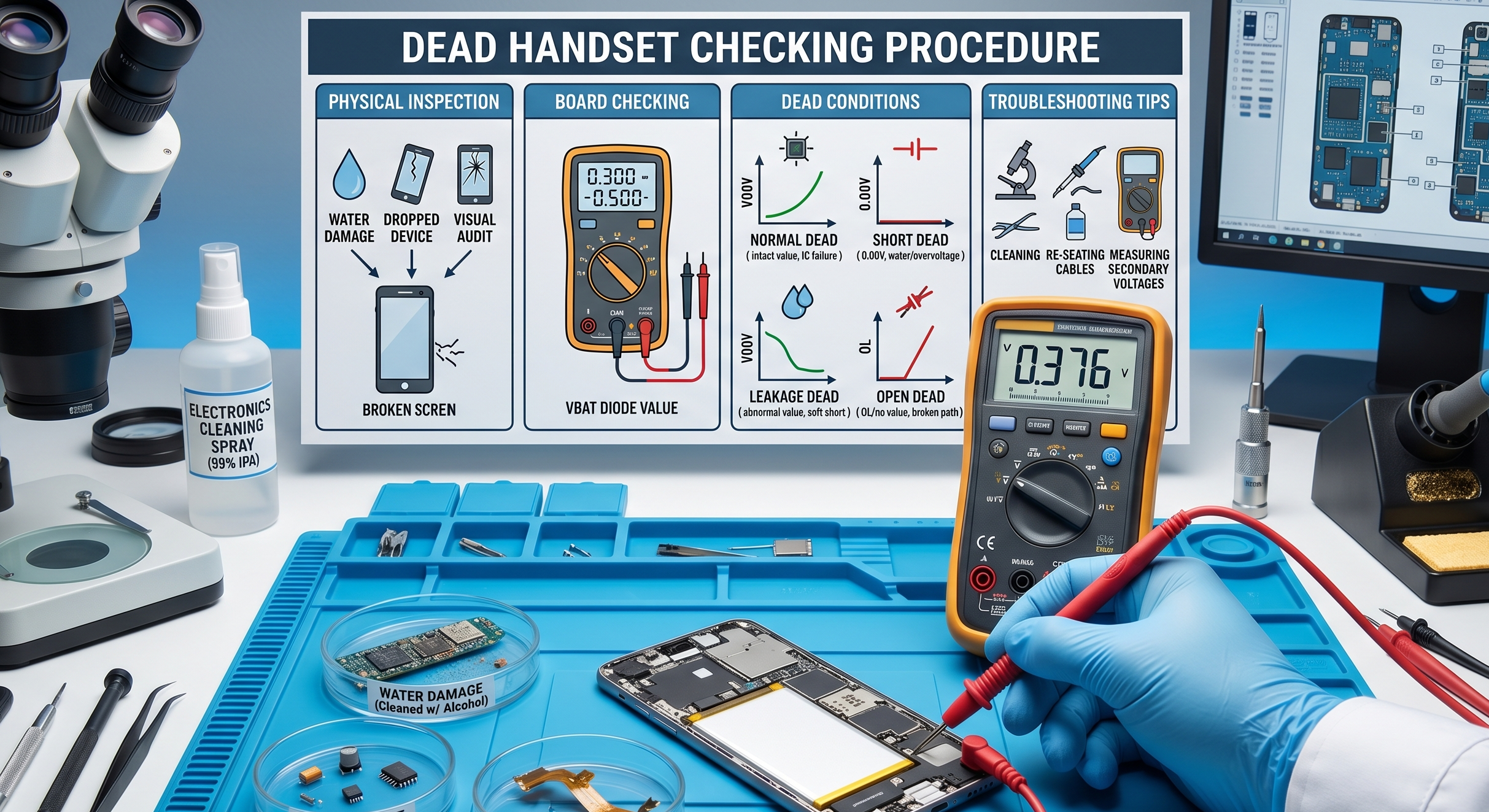
1. Preliminary Physical Inspection
Before testing electrical components, always assess the phone’s physical history to narrow down the potential fault.
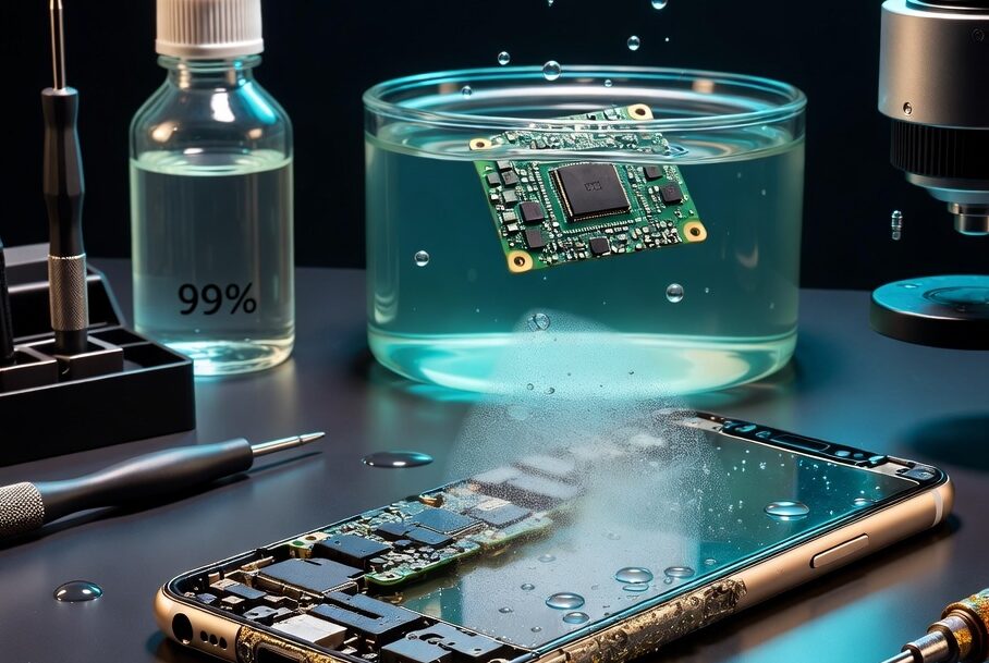
- Water Damage: If moisture exposure is suspected, disconnect the battery and all flex cables from the motherboard immediately. Clean the motherboard and all flexes using thinner, alcohol, or 530 cleaning spray.
- Physical Impact (Drops): For phones that have fallen, disconnect and reconnect all flex cables, as connectors may have become unseated.
- Visual Board Audit: Carefully inspect the motherboard for broken or missing components and examine all flex cables for tears or damage.
2. Board Checking: Battery Connector Resistance
After the initial physical check, use a multimeter to measure the ground resistance (diode value) at the battery connector. This measurement typically reveals one of four primary conditions:
| Condition | Description | Typical Diode Value |
| Normal | Battery connection is electrically sound. | 0.300 – 0.500 |
| Short | VBAT is directly connected to Ground. | 0.00 (Zero resistance) |
| Leakage | Abnormal resistance; not a full short. | Low/Abnormal value |
| Open | The circuit path is broken. | OL (Open Line) |
Standard Diode Values by Model
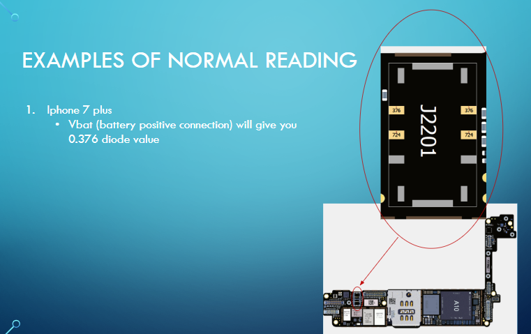
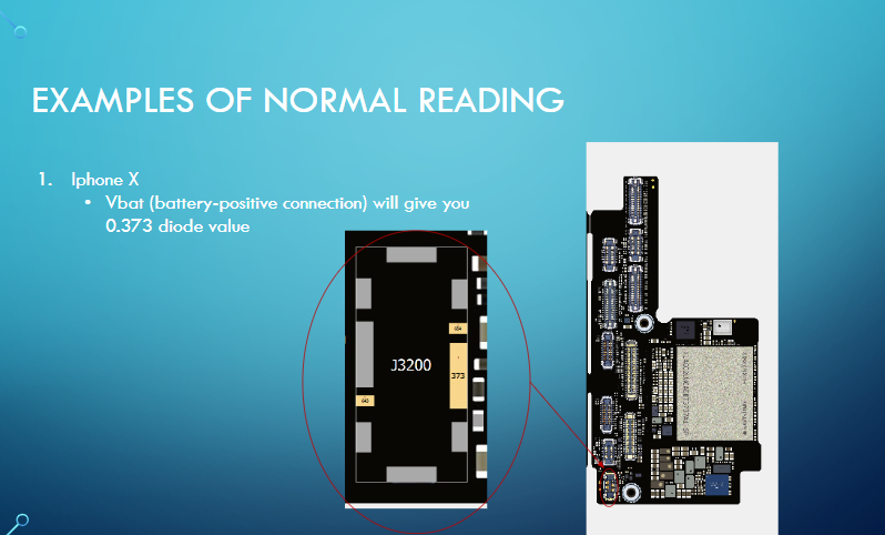
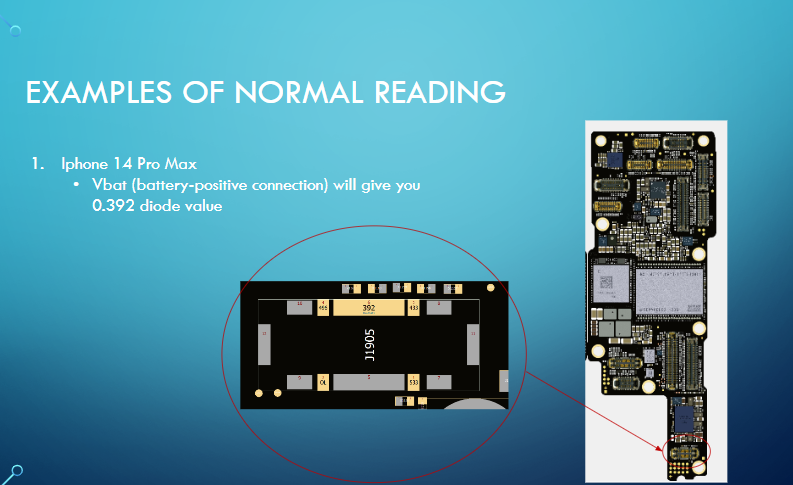
Most phones exhibit a normal diode value around 0.4xx. Specific examples of normal VBAT readings include:
iPhone 7 Plus: 0.376
iPhone X: 0.373
iPhone 14 Pro Max: 0.392
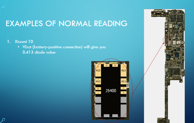
Xiaomi 10: 0.413
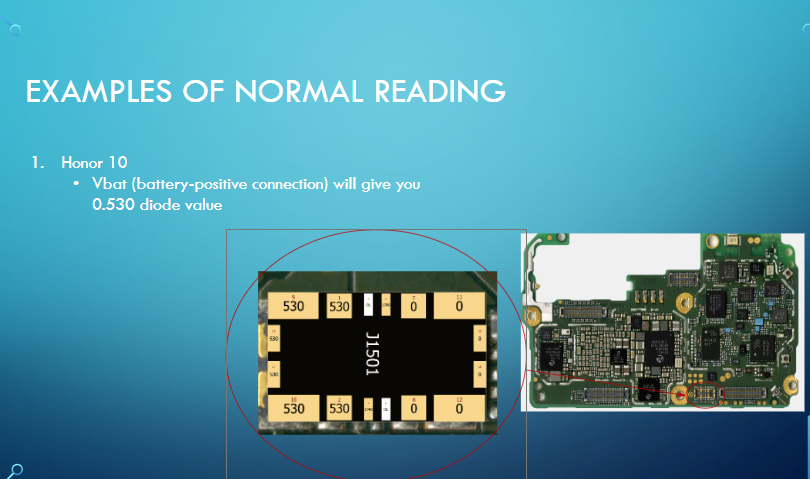
Honor 10: 0.530
3. Understanding “Dead” Conditions
Normal Dead
A “Normal Dead” handset has an intact battery connection but still fails to power on.
- Possible Causes: Faulty main voltages, missing signals, or the failure of a “Main IC” (integrated circuits essential for basic operation).
Short Dead
In this state, the battery’s positive voltage (VBAT) is directly connected to the ground.
- Causes: Water damage or overvoltage from faulty charging.
- Troubleshooting: You must identify the shorted component, which is often a parallel component in the circuit path or a faulty IC.
Leakage Dead
Leakage is a “soft short” where the connection to the ground is indirect.
- Characteristics: It typically involves a short in a secondary voltage path derived from the battery, rather than the VBAT path itself. Depending on the intensity of the leakage, some phones may still power on.
Open Dead
An “Open Dead” handset indicates a broken connection in the VBAT path.
Causes: This is generally caused by a “dry connection” (fractured solder joint) or a missing series component in the power circuit. No value will be displayed on the multimeter (OL).
Bringing Dead Smartphones Back to Life
Diagnosing a completely unresponsive mobile phone requires moving away from guesswork and adopting a precise, highly systematic approach. Modern smartphones are complex micro-computers, and finding the root cause of a “dead” handset means tracing faults through layers of circuitry. Here is a definitive guide to diagnosing and resolving dead motherboard issues, blending standard electrical procedures with the latest technological advancements in the repair industry.
Phase 1: Preliminary Inspection and Triage
Before touching a multimeter, the physical history of the device must be established. A visual audit often saves hours of unnecessary testing.
- Liquid Damage: If a phone is water-damaged, the battery and all flex cables must be disconnected immediately. The motherboard and flex cables should then be thoroughly cleaned using thinner, alcohol, or 530 cleaning spray to halt corrosion.
- Impact Damage: For phones that have been dropped, the first step is to disconnect and reconnect all flex cables, as the impact may have simply dislodged a connector. Next, the motherboard must be carefully inspected for physically broken or missing surface-mount components.
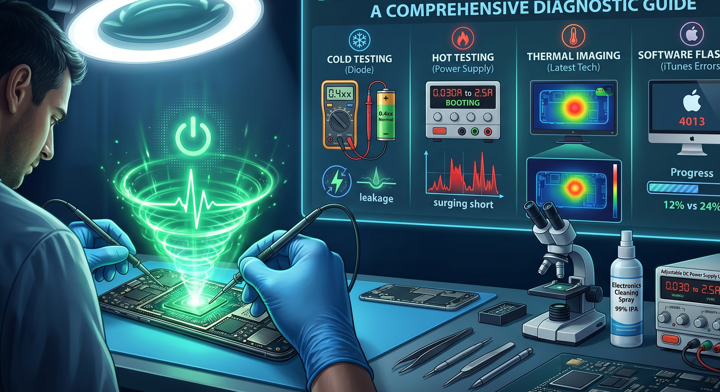
Phase 2: “Cold Testing” (Diode Mode Board Checking)
Once the board is clean, technicians perform “cold testing” (testing without power applied) by measuring the ground resistance, or diode value, at the battery connector. Normally, most phones will display a diode value around 0.4xx. For context, normal VBAT (battery positive) readings are 0.376 for the iPhone 7 Plus, 0.373 for the iPhone X, 0.392 for the iPhone 14 Pro Max, 0.530 for the Honor 10, and 0.413 for the Xiaomi 10.
This measurement will reveal one of four primary board conditions:
- Short Dead: The VBAT connection is shorted directly to the ground, resulting in a 0.00 resistance value. This catastrophic failure is mainly caused by water damage or overvoltage from a charger, usually due to a failed parallel component or integrated circuit (IC).
- Leakage Dead: The battery connector shows an abnormally low diode value. Unlike a direct short, this indicates a voltage short on a secondary line derived from the battery, rather than the main VBAT path. Depending on the intensity of the leakage, some phones might still manage to power on.
- Open Dead: The multimeter reads “OL” (Open Line), meaning the VBAT circuit is physically severed. This is typically caused by a dry, fractured solder connection or a missing series component that has been knocked off the board.
- Normal Dead: The battery path shows a completely healthy diode value, yet the phone refuses to boot. This is often the most complex condition to troubleshoot.
Phase 3: Deep Dive into the “Normal Dead” Condition
If the primary power delivery is intact, a “Normal Dead” handset indicates that either a main IC has failed, or critical voltages and signals required for the boot sequence are missing.
Analyzing Main Voltages and Signals
A technician must probe the board to ensure secondary systems are receiving power. Key areas include:
- Primary Power Rails: Checking lines like Vbat/pp_batt_vcc, PP_VDD_MAIN, and PP_VDD_BOOST.
- CPU and RAM Voltages: The processor needs specific voltages to wake up, such as PP_CPU_VAR, PP_GPU_VAR, PP_SOC_VAR, and PP1V8_SDRAM.
- Storage Voltages: The NAND flash memory requires rails like PP3V0_NAND and PPOV9_NAND.
- Clock Signals: The CPU synchronizes its operations using a clock signal generated by a crystal oscillator (typically 24MHz or 32.768kHz). Technicians can verify if this oscillator is pulsing correctly using a Digital Storage Oscilloscope (DSO).
Phase 4: “Hot Testing” via DC Power Supply
By injecting power directly into the motherboard using an Adjustable DC Power Supply, technicians can observe the boot current to isolate failures. A normally booting phone will draw a fluctuating current between 0.30mA and 2.5A. Abnormal behaviors include:
- Stuck at Low Current (30mA to 200mA): This points to a digital or logic failure. The device should be connected to a PC. If detected in DFU mode, a firmware flash should be attempted. If it appears in “Blank DFU Mode” (showing only the ECID on software like 3uTools), the CPU likely requires reballing. If the PC does not detect the phone at all, the fault may lie with the USB Controlling IC, NAND, or missing CPU voltages originating from the Power IC.
- Surging to High Current (1.0A to 2.0A): This indicates a severe short on a main voltage line. The technician must inspect and remove shorted capacitors near the NAND or Power IC.
- Current Drops to Zero on Button Release: If the phone draws power only while the power button is held, check for shorted capacitors near the Power IC. If the capacitors are fine, the Power IC itself must be reballed or replaced.
Phase 5: Software Flash Diagnostics (iTunes Errors)
When attempting to restore a stuck device, standard iTunes/flashing errors serve as excellent diagnostic roadmaps:
- Error 1: Points to hardware faults in the EEPROM IC, Baseband CPU, or Power IC.
- Error 9: Commonly caused by physical NAND damage; the NAND IC usually requires replacement.
- Error 14: Suggests an issue with the USB Controlling IC (Tristar/Hydra) or the NAND.
- Errors 21, 27, 29: Indicate a breakdown in battery communication or the battery data path.
- Error 4013: Frequently caused by dry connections beneath the NAND; reballing the NAND IC typically resolves this.
- Error 4014: If the error occurs before 12% completion, check the CPU and RAM; if it hits at 24%, the fault lies with the NAND connections.
Phase 6: The Latest Advancements in Motherboard Diagnostics
While multimeters and schematics remain the foundation of board repair, modern technicians now utilize advanced tools to diagnose the incredibly dense “sandwich” (dual-layer) motherboards found in flagship devices today:
- Infrared Thermal Imaging: This is arguably the biggest leap in modern mobile repair. Instead of injecting voltage and using evaporating rosin smoke to guess where a short is hiding, technicians now use high-resolution thermal cameras. When a tiny voltage is injected into a shorted line, the faulty capacitor or IC immediately glows white-hot on the camera monitor, pinpointing the exact component in seconds.
- Smart Power Supplies & Data Analyzers: Modern DC power supplies do more than just provide voltage; they connect to PC software to graph the boot sequence in real-time. By comparing the live current-draw curve of a dead phone against the known-good curve of a working phone, technicians can spot exactly when a boot sequence fails (e.g., distinguishing an I2C line failure from a RAM initialization failure).
- Pre-Heaters and Motherboard Separation Fixtures: Modern logic boards (like those in recent iPhones) are stacked in two halves soldered together. Specialized, temperature-controlled separation platforms are now mandatory. These tools melt the interposer solder evenly, allowing technicians to split the board without damaging the delicate CPU or Baseband components inside, which is required before any micro-soldering or diode testing can even begin on the inner layers.